Getting started with labview
Posted by Unknown on Tuesday, August 27, 2013 with No comments
Lab-view (Laboratory Virtual Instrument Engineering Workbench) is a graphical programming language that uses icons instead of lines of text to create applications. In contrast to text-based programming languages, where instructions determine the order of program execution, Lab-view uses data flow programming, where the flow of data through the nodes on the block diagram determines the execution order of the VI's and functions. VI's, or virtual instruments, is Lab-view programs that imitate physical instruments.
Lab-view programs are called virtual instruments, or VI's, because their appearance and operation imitate physical instruments, such as oscilloscopes and multi meters. Lab-view contains a comprehensive set of tools for acquiring, analyzing, displaying, and storing data, as well as tools to help you troubleshoot code you write.
In Lab-view, you build a user interface by using a set of tools and objects. The user interface is known as the front panel. After you build the front panel, you add code using graphical representations of functions to control the front panel objects. You add this graphical code, also known as G code or block diagram code, to the block diagram. In some ways, the block diagram resembles a flowchart.
In Lab-view, you build a user interface, or front panel, with controls and indicators. Controls are knobs, push buttons, dials, and other input mechanisms. Indicators are graphs, LED's, and other output displays. After you build the user interface, you add code using VI's and structures to control the front panel objects.
Overview of lab-view and its tools:
Lab-view programs are called virtual instruments (VI's).Each VI contains three main parts:
• Front Panel – How the user interacts with the VI.
• Block Diagram – The code that controls the program.
• Icon/Connector – Means of connecting a VI to other VI's.

Front panel:
The Front Panel is used to interact with the user when the program is running. Users can control the program, change inputs, and see data updated in real time. Stress that controls are used for inputs- adjusting a slide control to set an alarm value, turning a switch on or off, or stopping a program. Indicators are used as outputs. Thermometers, lights, and other indicators indicate values from the program. These may include data, program states, and other information.
Every front panel control or indicator has a corresponding terminal on the block diagram. When a VI is run, values from controls flow through the block diagram, where they are used in the functions on the diagram, and the results are passed into other functions or indicators.
Block diagram:
After you build the front panel, you add code using graphical representations of functions to control the front panel objects. The block diagram contains this graphical source code, also known as G code or block diagram code. Front panel objects appear as terminals on the block diagram.
Icon/Connector:
After you build a VI front panel and block diagram, build the icon and the connector pane so you can use the VI as a sub VI. The icon and connector pane correspond to the function prototype in text-based programming languages. Every VI displays an icon, such as the one shown as follows, in the upper right corner of the front panel and block diagram windows..

A VI icon is a graphical representation of a VI. It can contain text, images, or a combination of both. If you use a VI as a sub VI, the icon identifies the sub VI on the block diagram of the VI. If you add the VI to the palette, the VI icon also appears on the Functions palette. You can double-click the icon in the front panel window or block diagram window to customize or edit it.
You also need to build a connector pane, shown as follows, to use the VI as a sub VI.
The connector pane is a set of terminals that correspond to the controls and indicators of that VI, similar to the parameter list of a function call in text-based programming languages. The connector pane defines the inputs and outputs you can wire to the VI so you can use it as a sub VI. A connector pane receives data at its input terminals and passes the data to the block diagram code through the front panel controls and receives the results at its output terminals from the front panel indicators.
Tools palette:

If Automatic tool selection is enabled and you move the cursor over objects on the front panel or block diagram, Lab-view automatically selects the corresponding tool from the Tools palette. Toggle automatic tool selection by clicking the Automatic Tool Selection button in the Tools palette or by pressing the <Shift-Tab> keys. In this class we will discuss the four most common tools in Lab-view: The Operating, Positioning/Re-sizing, Labeling, and Wiring Tools.
Use the Operating tool to change the values of a control or select the text within a control.
Use the Positioning tool to select, move, or re-size objects. The Positioning tool changes shape when it moves over a corner of a re-sizable object.
Use the Labeling tool to edit text and create free labels.The Labeling tool changes to a cursor when you create free labels.
Use the Wiring tool to wire objects together on the block diagram.
When automatic tool selection is disabled, you can alternate among tools on the Tools palette, by pressing the <Tab> key. To toggle between the Positioning and Wiring tools on the block diagram or the Positioning and Operating tools on the front panel, press the space bar.
Status toolbar:
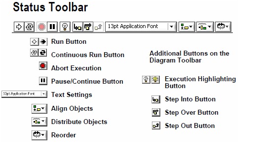
Click the Run button to run the VI. While the VI runs, the Run button appears with a black arrow if the VI is a top-level VI, meaning it has no callers and therefore is not a sub VI.
Click the Continuous Run button to run the VI until you abort or pause it. You also can click the button again to disable continuous running.
While the VI runs, the Abort Execution button appears. Click this button to stop the VI immediately.
Note: Avoid using the Abort Execution button to stop a VI. Either let the VI complete its data flow or design a method to stop the VI programmatically. By doing so, the VI is at a known state. For example, place a button on the front panel that stops the VI when you click it.
Click the Pause button to pause a running VI. When you click the Pause button, Lab-view highlights on the block diagram the location where you paused execution. Click the Pause button again to continue running the VI.
Select the Text Settings pull-down menu to change the font settings for the VI, including size, style, and color.
Select the Align Objects pull-down menu to align objects along axes, including vertical, top edge, left, and so on.
Select the Distribute Objects pull-down menu to space objects evenly, including gaps, compression, and so on.


0 comments:
Post a Comment