Think beyond.... Make it true...

  • Software Project

    JAVA projects, Dot net projects, web development projects & Andriod projects, android application developing projects

    Read More
  • Electrical Project

    Power electronics projects, drives projects, control system projects, convertors, invertors & power electronics simulation and hardware projects

    Read More
  • Embedded Project

    8051, PIC, ARM, ARM CORTEX, MSP430, & ATMEGA microcontroller projects and RTOS (Real time operating system) projects, embedded linux projects and sensor interfacing projects

    Read More

Friday, August 30, 2013

POWER ELECTRONICS GETTING STARTED RECTIFIER

Types of Converters in Power Eletronics

1. AC-DC CONVERTER
2. DC-AC CONVERTER
3. DC-DC CONVERTER
4. AC-AC CONVERTER

AC-DC CONVERTER:

1.Diode Rectifiers


Introduction:

Rectifier is concerned with the application and design of diode rectifier circuits. It covers single-phase, three-phase,poly-phase and high-frequency rectifier circuits.
 Theobjectives of this chapter are:

  • To enable readers to understand the operation of typical   rectifier circuits.
  • To enable readers to appreciate the different qualities of rectifiers required for different applications.
  • To enable the reader to design practical rectifier circuits.

Single-Phase Diode Rectifiers

             There are two types of single-phase diode rectifier that convert a single-phase ac supply into a dc voltage, namely, single-phase half-wave rectifiers and single-phase full-wave rectifiers. In the following subsections, the operations of these rectifier circuits are examined and their performances are analyzed and compared in tabular form. For the sake of simplicity the diodes are considered to be ideal, that is, they have zero forward voltage drop and reverse recovery time. This assumption is generally valid for the case of diode rectifiers that use the mains, a low-frequency source, as the input, and when the forward voltage drop is small compared with the peak voltage of the mains. Furthermore, it is assumed that the load is purely
resistive such that load voltage and load current have similar waveforms.

Single-Phase Half-Wave Rectifiers


          The simplest single-phase diode rectifier is the single-phase half-wave rectifier. A single-phase half-wave rectifier with resistive load. The circuit consists of only one diode that is usually fed with a transformer second-ary as shown. During the positive half-cycle of the transformer secondary voltage, diode D conducts. During the negative half-cycle, diode D stops conducting. Assuming that the transformer has zero internal impedance and provides perfect sinusoidal voltage on its secondary winding, the voltage and current waveforms of resistive load R and the voltage wave-form of diode D are shown in Figure. By observing the voltage waveform of diode D in Figures, it is clear that the peak inverse voltage (PIV) of diode D is equal to Vm during the negative half-cycle of the transformer secondary voltage. Hence the Peak Repetitive Reverse Voltage (VRRM) rating of diode D must be chosen to be higher than Vm to avoid reverse breakdown. In the positive half-cycle of the transformer second-ary voltage, diode D has a forward current which is equal to the load current and, therefore, the Peak Repetitive Forward Current (IFRM) rating of diode D must be chosen to be higher than the peak load current Vm=R, in practice. In addition, the transfor-mer has to carry a dc current that may result in a dc saturationproblem of the transformer core.


Thanks for saravanan for this valuable post


Mob    :       +91-9790766717
                   +91-9500087478
Web    :       www.masterychip.com
Mail     :       projects@masterychip.com

Tuesday, August 27, 2013

Getting started with labview


Lab-view (Laboratory Virtual Instrument Engineering Workbench) is a graphical programming language that uses icons instead of lines of text to create applications. In contrast to text-based programming languages, where instructions determine the order of program execution, Lab-view uses data flow programming, where the flow of data through the nodes on the block diagram determines the execution order of the VI's and functions. VI's, or virtual instruments, is Lab-view programs that imitate physical instruments.

Lab-view programs are called virtual instruments, or VI's, because their appearance and operation imitate physical instruments, such as oscilloscopes and multi meters. Lab-view contains a comprehensive set of tools for acquiring, analyzing, displaying, and storing data, as well as tools to help you troubleshoot code you write.

In Lab-view, you build a user interface by using a set of tools and objects. The user interface is known as the front panel. After you build the front panel, you add code using graphical representations of functions to control the front panel objects. You add this graphical code, also known as G code or block diagram code, to the block diagram. In some ways, the block diagram resembles a flowchart.

In Lab-view, you build a user interface, or front panel, with controls and indicators. Controls are knobs, push buttons, dials, and other input mechanisms. Indicators are graphs, LED's, and other output displays. After you build the user interface, you add code using VI's and structures to control the front panel objects.

Overview of lab-view and its tools:

Lab-view programs are called virtual instruments (VI's).Each VI contains three main parts:
       
• Front Panel – How the user interacts with the VI.
• Block Diagram – The code that controls the program.
• Icon/Connector – Means of connecting a VI to other VI's.


Front panel:

The Front Panel is used to interact with the user when the program is running. Users can control the program, change inputs, and see data updated in real time. Stress that controls are used for inputs- adjusting a slide control to set an alarm value, turning a switch on or off, or stopping a program. Indicators are used as outputs. Thermometers, lights, and other indicators indicate values from the program. These may include data, program states, and other information.
Every front panel control or indicator has a corresponding terminal on the block diagram. When a VI is run, values from controls flow through the block diagram, where they are used in the functions on the diagram, and the results are passed into other functions or indicators.

Block diagram:

After you build the front panel, you add code using graphical representations of functions to control the front panel objects. The block diagram contains this graphical source code, also known as G code or block diagram code. Front panel objects appear as terminals on the block diagram.

Icon/Connector:

After you build a VI front panel and block diagram, build the icon and the connector pane so you can use the VI as a sub VI. The icon and connector pane correspond to the function prototype in text-based programming languages. Every VI displays an icon, such as the one shown as follows, in the upper right corner of the front panel and block diagram windows..


A VI icon is a graphical representation of a VI. It can contain text, images, or a combination of both. If you use a VI as a sub VI, the icon identifies the sub VI on the block diagram of the VI. If you add the VI to the palette, the VI icon also appears on the Functions palette. You can double-click the icon in the front panel window or block diagram window to customize or edit it.

You also need to build a connector pane, shown as follows, to use the VI as a sub VI.

The connector pane is a set of terminals that correspond to the controls and indicators of that VI, similar to the parameter list of a function call in text-based programming languages. The connector pane defines the inputs and outputs you can wire to the VI so you can use it as a sub VI. A connector pane receives data at its input terminals and passes the data to the block diagram code through the front panel controls and receives the results at its output terminals from the front panel indicators.

Tools palette:


          If Automatic tool selection is enabled and you move the cursor over objects on the front panel or block diagram, Lab-view automatically selects the corresponding tool from the Tools palette. Toggle automatic tool selection by clicking the Automatic Tool Selection button in the Tools palette or by pressing the <Shift-Tab> keys. In this class we will discuss the four most common tools in Lab-view: The Operating, Positioning/Re-sizing, Labeling, and Wiring Tools.

Use the Operating tool to change the values of a control or select the text within a control.

Use the Positioning tool to select, move, or re-size objects. The Positioning tool changes shape when it moves over a corner of a re-sizable object.

Use the Labeling tool to edit text and create free labels.The Labeling tool changes to a cursor when you create free labels.

Use the Wiring tool to wire objects together on the block diagram.

When automatic tool selection is disabled, you can alternate among tools on the Tools palette, by pressing the <Tab> key. To toggle between the Positioning and Wiring tools on the block diagram or the Positioning and Operating tools on the front panel, press the space bar.

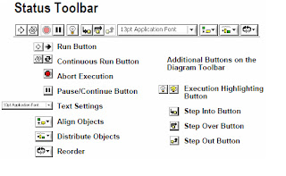
Status toolbar:


          Click the Run button to run the VI. While the VI runs, the Run button appears with a black arrow if the VI is a top-level VI, meaning it has no callers and therefore is not a sub VI.

Click the Continuous Run button to run the VI until you abort or pause it. You also can click the button again to disable continuous running.

While the VI runs, the Abort Execution button appears. Click this button to stop the VI immediately.

 Note: Avoid using the Abort Execution button to stop a VI. Either let the VI complete its data flow or design a method to stop the VI programmatically. By doing so, the VI is at a known state. For example, place a button on the front panel that stops the VI when you click it.

Click the Pause button to pause a running VI. When you click the Pause button, Lab-view highlights on the block diagram the location where you paused execution. Click the Pause button again to continue running the VI.

Select the Text Settings pull-down menu to change the font settings for the VI, including size, style, and color.

Select the Align Objects pull-down menu to align objects along axes, including vertical, top edge, left, and so on.

Select the Distribute Objects pull-down menu to space objects evenly, including gaps, compression, and so on.


Mob    :       +91-9790766717
                   +91-9500087478
Web    :       www.masterychip.com
Mail     :       projects@masterychip.com

Monday, August 26, 2013

Smart phone controlled smart car


I built a wireless robotics platform from a cheap R/C car, an 8051 micro-controller with Bluetooth module, and a Processing program running on a micro-controller to control the vehicle. The vehicle is completely controlled by android smart phone which allows very rapid prototyping of the code to tell the vehicle what to do and how to react to the commands from android smart phone via Bluetooth. I’m hoping this is a good way to teach to 9-year old boy about programming.

It’s the most basic example of adding small intelligence to a robot, but it’s actually the designer’s intelligence!!
Before I get into details, here’s an overview of the features:
All logic controlling the vehicle is performed in a Processing program running on android mobile phone. The microcontroller program listens for commands from the android phone.
Bi-directional wireless communication performs over a Bluetooth protocol. It’s as simple as connecting the RX/TX pairs together, and giving it power. This vehicle has two 12Vmotors with 3 control signals namely, forward, right and left

 An android smart phone consists of an application to control the car using built-in Bluetooth  

          Inside the vehicle is a simple relay circuit board with microcontroller board and Bluetooth. The 12V dc motor of 100 rpm is used in this smart car

Power: Vehicle motors, 8051 microcontroller, relay circuit and Bluetooth module powered by 12V 7.5 ah lead acid battery.


The final smart car driving at night....................


LIGHT EMITTING DIODE Interfacing tutorial


        Light Emitting Diodes (LED) is the most commonly used electronic components, generally for display digital states. Typical uses of LED's include alarm devices, timers and confirmation of user input such as a mouse click or keystroke, events etc. LED's are very cheap and easily available in a variety of shape, size and colors.

        89C51, which belongs to the family of 8051 series of micro-controllers  is very commonly used by a large community of hobbyist and engineers. Its simplicity and ease of programming with inbuilt features easily makes its position in the top preferred list of micro-controller for both beginners and advanced user.
To connect a led refer the methods of connection here

        You can use 10-15 mA as a safe LED current which will provide decent light intensity and conserve battery power. Determine the Series resistor using Ohms law with an excess voltage value and current value for LED. Red LED's generally need 1.5V to 1.9V to light any extra voltage must be dropped with a series resistor else the LED will draw extra current in an attempt to lower the supply voltage down to the 1.5V level. The typical supply voltage source for micro-controller is 5V.

Then, 5 - 1.7 = 3.3V of excess voltage.
Let’s design the LED to use 10mA
Ohms law Resistance R = V / I
3.3 / 10mA = 330 Ohms, Place a 330 ohm resistor in series with the LED.

Circuit Diagram

Interfacing Switch and LED with 8051

Interfacing Switch and LED with 8051

            This article is meant for beginners in the field of micro-controllers  When I started with micro-controllers as everyone I also need to learn how to interface a switch with micro-controller.


A switch is an electrical component that can break an electrical circuit, interrupting the current or diverting it from one conductor to another. A switch may be directly manipulated by a human as a control signal to a system, or to control power flow in a circuit.


A switch requires a pull-up or pull-down resistor to produce a definite high or low voltage when it is open or closed. A resistor placed between a digital input and the supply voltage is called a "pull-up" resistor because it normally pulls the pin's voltage up to the supply. 


Software Tools:

1.      RIDE Compiler (Evaluation version) 
2.      WINISP Down loader      (Free version ) 

Hardware:

1. P89C51
2. Push button switch
3. micro-controller board

Program:

#include<reg51.h>
sbit LED=P0^7; //port declaration
sbit SW1=P0^0;
sbit SW2=P0^1;
void main()
{
while(1)
{
if(SW1==0 || SW2==0) //if the SW1 or SW2 is pressed
{
LED=1;
}
else
LED=0;
}
}


Mob    :       +91-9790766717
                   +91-9500087478
Web    :       www.masterychip.com
Mail     :       projects@masterychip.com


Saturday, August 24, 2013

Sinking and Sourcing


Difference Between Sinking and Sourcing


Sinking and sourcing refer to the type of digital inputs and outputs used. A sinking digital I/O (input/output) provides a ground. A sourcing digital I/O provides a voltage source. 

Consider a simple circuit that consists of one digital input connected to a digital output. The circuit needs a voltage source, a ground, and a load. A sourcing digital I/O provides the voltage needed for the circuit. A sinking digital I/O provides the ground needed in the circuit. The digital input provides the load required for the circuit to work.

Figure 1 shows a sinking digital output that is connected to a sourcing digital input. In this circuit, the sourcing digital input provides the voltage and the load. The sinking digital output controls the line by using a transistor to leave the line high (at +V) or to ground the line to 0 V.

Figure 1: Sinking Digital Output Circuit
Figure 2 shows a sourcing digital output that is connected to a sinking digital input. In this circuit, the sourcing digital output provides the voltage and the sinking digital input provides the load and the ground. The digital output controls the line by using a transistor to leave the line at 0 V or to raise the line to +V.

Figure 2: Sourcing Digital Output Circuit

Because you need both a voltage source and a ground in order to create a complete circuit, you need to have a sourcing input or output connected to a sinking output or input. If you wish to connect a sourcing input to a sourcing output or a sinking input to a sinking output, you will need to add an additional resistor. For further information on connecting two I/O of the same type,


Mob    :       +91-9790766717
                   +91-9500087478
Web    :       www.masterychip.com
Mail     :       projects@masterychip.com

Thursday, August 22, 2013

LED Dot-matrix display

Driver MM5450


A dot-matrix display is a display device used to display information on machines, clocks and many other devices requiring a simple display device of limited resolution. Light emitting diodes aligned in a form of matrix constitute a dot matrix display. Arrangement of the LED's in the matrix pattern is made in either of the two ways: row anode-column cathode or row cathode-column anode. In row anode-column cathode pattern, the entire row is anode while all columns serve as cathode and vice-versa pattern is there in row cathode-column anode.


 A dot matrix controller converts instructions from a processor or controller into signals which turns on or off lights in the matrix so that the required display is produced. We covered how to interface seven segment LED displays to a micro-controller  Today, we will move on to interfacing an LED dot matrix display. LED dot matrices are very popular means of displaying information as it allows both static and animated text and images.

Perhaps, you have encountered them at gas stations displaying the gas prices, or in the public places and alongside highways, displaying advertisements on large dot matrix panels. In this experiment, we will discuss about the basic structure of a monochrome (single color  LED dot matrix and its interface with a micro-controller to display static characters and symbols. I am using the 89C51 micro-controller on for demonstration, but this technique is applicable to any other micro-controllers that have sufficient I/O pins to drive the LED matrix driver MM5450 through SPI protocol.

Click Here to watch youtube video


Mob    :       +91-9790766717
                   +91-9500087478
Web    :       www.masterychip.com
Mail     :       projects@masterychip.com

Followers

Disclaimer

The documents, software, tools and links are provided to enhance the ability of an electronics student, hobbyist or professional by sharing information. The information, links etc. should be used by the website visitor, at his or her own risk and responsibility. There may be concept, design and link errors in the pages.

My Creative Work, ideas and documents can be used for Product Design and Development by R&D Engineers, Hobbyists, Students and even firms for creating useful products. These cannot be used for reprint, replication or publishing online or offline.

Translate